3D printing gives engineers an enormous amount of design freedom. Complex geometries, lightweight structures, internal channels, and assemblies can all be produced in ways that are difficult—or sometimes impossible—with traditional manufacturing.
But printing a complex part and printing a part that can handle demanding structural loads are not always the same thing.
That is where Reinforce3D's Continuous Fiber Injection Process, better known as CFIP, offers a different approach. Instead of trying to add every performance requirement during the original manufacturing process, CFIP reinforces the completed part from the inside out.
Why Some 3D-Printed Parts Need More Than Infill
When a polymer part needs additional strength, the first instinct may be to add more material, increase wall thickness, or use a denser infill. These changes can help, but they can also add weight, increase print time, and use more material without placing reinforcement in the most effective locations.
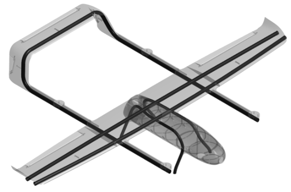
CFIP looks at the challenge differently. The process uses internal tubular cavities designed into the component. After the part has been manufactured, continuous fibers are inserted through those cavities and follow defined paths inside the geometry.
This allows reinforcement to be placed closer to the areas where loads are actually carried. Rather than making the entire component heavier, engineers can focus strength where it is needed most.
Reinforcement Becomes Its Own Manufacturing Step
One of the most interesting things about CFIP is that it is a post-process. The base component is manufactured first, and reinforcement is added afterward.
That distinction matters because it separates two important decisions:
- What is the best way to manufacture the part's shape?
- Where does the finished part need additional structural performance?
The base part can be designed for geometry, fit, weight, material use, and manufacturability. The internal fiber paths can then be planned around the loads the component is expected to experience.
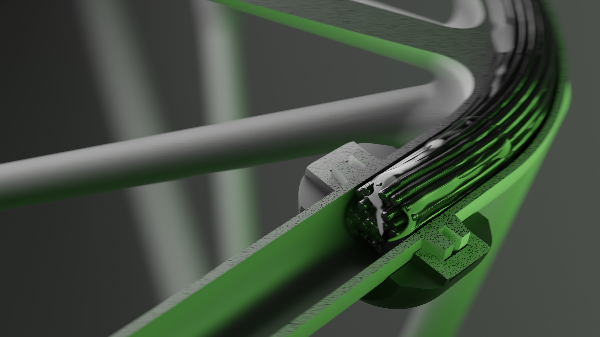
This approach also gives engineers more flexibility than a process in which the fiber must be deposited at the same time as the part. Reinforcement paths can travel through the interior of the component and are not limited to simply following each printed layer.
It Is Not Limited to One Printing Technology
CFIP is often discussed alongside additive manufacturing, but the idea is broader than reinforcing a part from one specific type of 3D printer. Reinforce3D describes the process as compatible with additive and molded components, with support for multiple reinforcement fibers and thermoplastics.
That makes CFIP worth considering as part of a larger manufacturing workflow rather than as a replacement for an existing printer or production method.
An engineer can begin with the process that makes the most sense for the component and then determine whether internal continuous-fiber reinforcement could help the part meet its performance goals.
In some applications, CFIP can also be used to reinforce and join separate sections with fiber continuity through the assembly. This creates new possibilities for larger components and multi-part structures that may be difficult to manufacture as one piece.
Where Could CFIP Make a Difference?
Not every printed part needs continuous-fiber reinforcement. A visual prototype, fit-check model, or lightly loaded component may already perform exactly as intended.
CFIP becomes especially interesting when a project is trying to balance competing requirements, such as:
- Reducing weight without giving up needed strength or stiffness
- Moving from a prototype toward a functional, load-bearing component
- Keeping a complex or lightweight geometry while improving performance
- Reinforcing specific load paths instead of adding material everywhere
- Joining multiple manufactured sections into a larger reinforced structure
- Exploring alternatives to heavier metal components or conventional composite production
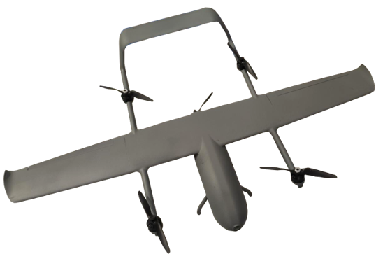
Potential applications can be found across aerospace, automotive, UAVs, industrial manufacturing, medical devices, and sports equipment—anywhere weight, geometry, and structural performance must be considered together.
CFIP Starts With the Design
Because the continuous fiber travels through internal cavities, CFIP is not simply a finishing step that can be applied to any geometry without planning. The part must be designed with manufacturable reinforcement paths, suitable cavity geometry, and the intended loads in mind.
That makes early application evaluation important. The real question is not only, "Can this part be reinforced?" It is also, "Where should the fiber go, what loads must the part carry, and what manufacturing process should be used for the base component?"
Answering those questions early can help teams identify strong candidate applications and avoid treating reinforcement as an afterthought.
Explore CFIP Technology With Impac Systems Engineering
As Reinforce3D's North American distributor, Impac Systems Engineering helps manufacturers understand where CFIP fits within a real additive manufacturing workflow.
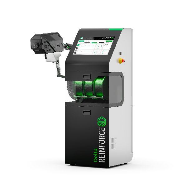
Our Reinforce3D DELTA system is installed at our Temple, Texas headquarters, giving customers the opportunity to see the continuous fiber injection process firsthand and discuss potential applications with our engineering team.
Whether you are developing an aerospace structure, UAV component, industrial tool, automotive part, or another lightweight load-bearing application, we can help you evaluate whether CFIP is a practical next step for your project.
The print may create the geometry—but with the right reinforcement strategy, it does not have to define the part's final performance.
Learn more about the Reinforce3D DELTA system: https://impacsystems.com/brands/delta/
Contact Impac Systems Engineering to discuss your application or schedule a demonstration: https://impacsystems.com/company/contact-us/